A
Simple DIY Indoor UHF TV Antenna
Update from the 2016 Original - April 2023
In preparation for, "Cutting the Cord," I needed a better antenna to replace the simple attic dipole plus reflector that I had been using for occasional OTA reception. Most of my local stations are UHF and only about 15 miles away. However, the old TV Fool showed my location to be 2nd-Edge for them, and with the simple antenna the strength of several of the signals, varied from the low end of, "Excellent," all the way down to, "No Signal," over a several minute period.
Some Internet research turned up the Gray-Hoverman antennas as providing good UHF gain while being much simpler to build than conventional 4 stack bow-ties, etc. I chose a computer-optimized one from a site that is no longer available. I liked it because it was optimized for channels 14 to 51 and, taking a few liberties with the design, could be constructed on two 24 X 36 inch 1/4 inch thick foam boards. A nice DIY project.
Materials list: The 2 foam boards, 20 feet of #16(not critical) wire, 1 foot of smaller wire (#20?), six 3" thick stryofoam spacer blocks, masking tape, hot glue, Gorilla glue. 300 Ohm to 75 Ohm balun.
Here is the basic Dimension Diagram.
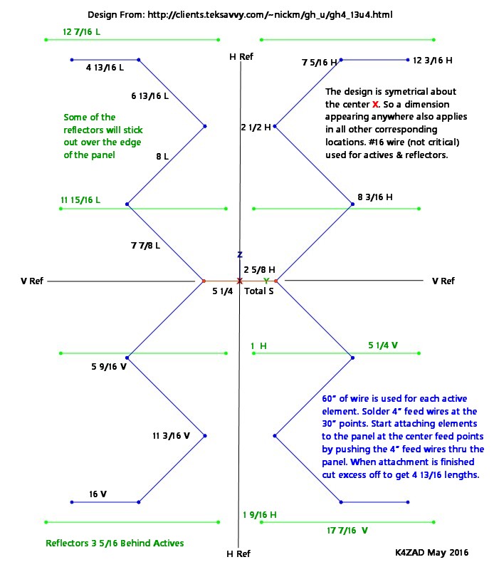
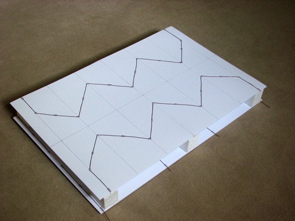
Using ink I put one horizontal and one vertical reference line on the active element panel. Then added vertical grid lines all the way across the panels at the vertical location of the bend points. The actual bend points were then located on the vertical grid lines by measuring out from the horizontal reference line. The location of the elements on the reflector panel was easily done by direct measurements. Masking tape was used to hold the wires in place on the panels prior to applying spots of hot glue to permanently hold them.
The 3 inch spacer blocks (cut from some old packing material) were hot-glued to the front of the reflector panel. Gorilla glue was applied to the face of the spacer blocks and the back of the active element panel was laid down on the blocks and carefully aligned. Stacks of books were placed on the panel over each block until the Gorilla glue cured. A hole was cut in the center of the reflector panel to access the 4" feed wires which were then soldered to the balun wires.
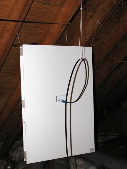
Rear view of completed antenna installed in the attic.
Also
see the construction detail photos below.
I
am pleased with the results. All signals are now normally in the middle
of the, "Excellent," range with variations to lower levels as seen with
the
previous antenna but the dips are not nearly as deep, and the pictures
are steady with no pixelation. Two of the local stations are now VHF-Hi and
also received OK on this antenna, though with low signal strength.
This antenna could not have been built without Nikolay
Mladenov's, no longer available, design
information. Many thanks to him for his many Gray-Hoverman
antenna designs.
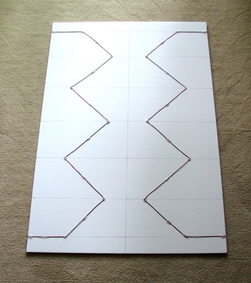
Active Element Panel
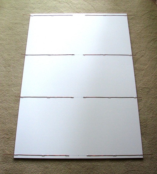
Reflector Element Panel
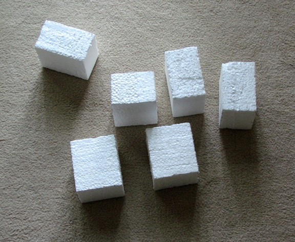
3 Inch Stryofoam Spacer Blocks
Completed Antenna
Contact Me
Back
to the Index Page
Main
Site - The Inland Marine Radio History Archive
Links checked and page code revised - 04/16/2023